
Please read and comment on the following fascinating article about SCVF problems written by my invited expert: Djilali Sahnoun – Technical & Engineering Manager.
Many wells experience surface casing vent flow (SCVF) and subsequent gas migration to the surface through one of the following issues: a cemented casing string(s) with either a micro-annulus between casing and cement, a channel within the cement sheath or a conduit between the applied and the borehole wall and annular gas migration can cause a variety of issues including:
- Interruption of production
- Abandonment regulation concerns
- Possible water contamination to underground or surface water
- Greenhouse gas emissions
- Fire hazards on the surface due to leaking gas
- Damage to reputation
The cost to repair a surface casing vent flow (SCVF) or gas migration (GM) can escalate due to other hidden or unknown sources of gas that may communicate with the existing channels. Other complications may arise including the combination of multiple gas sources, the relevant gas zone being tight or fragile, or the use of improper placement techniques and non-ideal cement systems. These complications result in reduced success rates which generate additional costs for the client, and in some instances, lead to secondary job failures.
The primary purpose of cementing is to form a permanent seal between the borehole wall and the casing. Good mud displacement practices are necessary to avoid mud channels in the cemented annulus which helps prevent gas flow and aids in attaining better cement bonds. Other factors affecting displacement efficiency and hole cleaning include centralization, pipe movement, spacer or preflush design, cement system selection and displacement rates.
An SCVF detected on the backside of the inner casing can be an indication of fluid or gas migration and movement within the annulus. The cause of this movement may be by many sources and factors which are hard to identify. Significant time and effort may be required to identify all the sources producing the migration.
Much of the SCVFs or sustained pressure on the surface casing are the result of events occurring to the cement sheath post-set. We should consider all activities planned within the wellbore life when designing a cement program as cement sheath damage can occur during cement placement, completion activities, well work-over operations or production. With this in mind, completion and drilling engineers must work together with the service companies to meet the requirements from the beginning of the well planning stage to ensure that we achieve formation isolation.
Gas migration typically occurs when gas flows through mud channels and filter cake deposits. Also, this can happen when shrinkage takes place as the cement transitions from its plastic state into a hardened state. As the cement shrinks, it pulls away from the mud filter cake, and it can also lose contact with the casing, leaving a microchannel for gas to flow through. A lack of seal may allow dry gas to flow through the moist channel of mud cake causing it to dry and to shrink, leaving an even larger flow channel. Shrinkage of 1% to 3% have been reported using different methods (annular ring mold and liner bar mold). In general, cement shrinkage directly relates to the calcium silicate crystals that form during hardening. Thus, this can be reduced or prevented by adding or using specific cementing materials and expanding agents in the cement design.
Even when we perform a primary cement job correctly, and post-job analysis has confirmed that all steps of the process are entirely according to the plan, the cement seal may slowly show failures or form internal cracks after days or years of well production. The cause of this deterioration is by various stresses implicated on the cement sheath. During the completion or production stage of the well, cyclic events may occur that can affect the cement sheath integrity through the effects of pressure, temperature, and remediation procedures.
The fluid flow can often be observed days after we perform the cement job. In most cases, the flow volume starts very small and can easily be bled off, but the problem may increase with time. Even abandoned wells can eventually leak. Again, the procedures used for well abandonments have not changed much in the last 20 years. The process typically includes a bridge plug with cement on top or a simple squeezing of a balanced cement plug. The abrasive jetting solution along with a properly planned cement squeeze can make a difference in changing these statistics over time.
Furthermore, in many areas, the first 400 m of the formation consists of gravel beds, silts and undeveloped shale with swelling clays. These formation conditions make it challenging to maintain borehole stability and isolation. The shallow formations are mostly unconsolidated, impairing the ability to achieve an excellent bond to the formation.
The low well temperatures can lead to long transition times when the cement is setting, allowing more opportunity for gas or fluid to migrate up the annulus and cause a permanent channel. Non-economic gas sources uphole, known as shallow gas bearing zones, are possible sources for migration. This, coupled with low hydrostatic pressures due to the depth of these formations, adds to the challenge. Finally, the hole and casing size is large, due to the production strategy, which makes centralization and pipe movement during the cement job more difficult. Which in turn increases the risk to the cement job through a reduction in displacement efficiency.
Abrasive Jetting and Cement Squeeze Solution
The customized remediation process concerns the challenges that we covered previously. Explosive perforating with a designated number of shots has a limited performance for SCVF repair. Perforating is relatively inexpensive and straightforward; however, unlike abrasive cutting, it does not allow access to a full 360° around the casing to maximize exposure and penetration beyond the damaged zone. Furthermore, when using abrasive jetting, as compared to perforating, there is a reduction of fracture initiation on the cement sheath and no skin damage.
Another standard procedure to remedy a SCVF issue is milling and under-reaming. This provides the desired full coverage of the zone by cutting out a section of casing. The downfalls to milling and under-reaming are the cost of steel cutting and the complication of the operation. In some instances, the process is not as desirable as cutting a complete section of casing out since this makes it difficult for re-entry.
The complete abrasive jetting and cement squeeze process differs from traditional methods and consists of:
- Formation Evaluation
The formation is evaluated using log analysis such as noise logs and density neutron logs to identify possible gas sources and the shallowest caprock formation, which will help determine an ideal cutting point. Caprock formations are impermeable shale or calcareous shale that prevents gas migration after isolating the passage between borehole wall and casing (Figure 1). In some cases, multiple gas sources below the caprock formation may be ignored, which allows for cost-effective treatment of the shallowest impermeable zone while meeting regulatory and environmental requirements.
- Hydraulic Abrasive Jetting
Hydraulic abrasive jetting involves cutting slots on the horizontal plane to achieve communication with the formation. The process includes cutting through the casing, cement, and out into the formation. The process is completed by rotating the tool 120° while cutting with opposing jets. This is followed by two or more overlapped cuts to obtain complete 360° borehole coverage and expose the adjacent formation; ensuring gas is intercepted at the passage.
The cutting process is accomplished by the erosive action of high-velocity flow rates through jets and an abrasive particulate such as sand, which is mixed with fluid and forced through nozzles under sufficient hydraulic pressure. This process successfully cuts away casing, cement and formation.
Velocity may need to be much higher during the cutting operation. Also, it is worth mentioning that it is essential to keep the return line wholly open and free of restrictions including elbows. These restrictions will significantly increase erosion in this piping.
- Formation Injectivity Test
The formation feed rate is the next step to be determined by performing a formation injectivity test. This is done following the cuts and displaces the well over to fresh water or compatible formation fluid. The injection test is typically done by staging fluid volumes and slowly increasing the pressure until we achieve the point of fracture initiation or a pre-determined pressure.
At this point, an operator can evaluate the rates and the pressures at which we will pump the selected fluid into the treatment zone. There is also an opportunity to utilize acid, or other stimulation techniques, to increase the feed rate in case the results are not sufficient to squeeze cement into the zone.
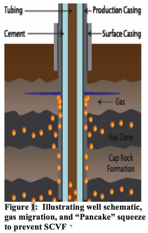
Figure 1: Illustrating well schematic, gas migration, and “Pancake squeeze to prevent SCVF
- Equipment & Fluid Selection
Once the abrasive cutting has been completed and a feed rate has been established, the next step in the process is to select appropriate products utilizing the proper techniques. This step can be challenging as some products that fit the criteria for a given wellbore situation (or feed rate), may not be applied through certain techniques. Therefore these characteristics must complement each other.
- Product selection
Typically, when abrasive jetting is utilized, the achieved feed rate is often relatively low. If the feed rate is <100 L/min at the maximum allowable pump pressure, micro-fine cement is commonly used. Depending on the technique determined to be used, a combination of two blends cement situation may also be used in order to ensure that we reduce costs, the required strength requirements are met, and slurry performance meets the goal of the operation. The lead cement may be the micro-fine cement followed by a standard Class ‘G’, or ‘H’, cement slurry. Because there may be significant differential pressure put on the cement, cement slurry with low fluid loss and short transition time is typically used. This is an effort to have the cement set in the desired location.
- Squeeze Techniques (hesitation or continuous)
The pumping procedures follow either a hesitation or continuous pumping technique during the squeeze operation. In the hesitation squeeze method, the pump is shut off for a period to allow the cement slurry to begin to develop gel strength. In a continuous pumping technique, the slurry is continuously pumped to prevent the gel strength from developing. This may create a challenge with either the amount of volume of slurry available to be being squeezed or the pressure will continually increase. Both situations can typically be dealt with through a reduction of pump rate. If the volume is being reduced without any signs of a pressure increase, the hesitation method can also be used at the end of the continuous pumping technique.
- Pumping Equipment (slow-rate or conventional)
The slow-rate pumping system is designed so that cement can be squeezed into a formation at times up to the cement’s thickening time. The slow-rate pump continuously forces slurry into the formation and can operate safely above a formation’s fracture pressure.
In certain conditions, the slow-rate theory indicates the cement will be flowing right on the tip of any extending fracture until the thickening time of the cement is reached. When there is too much resistance to the flow of cement in a given fracture, the pressure will climb until the cement flows into another fracture that begins extending, and so on. The cement can be on the tip of multiple extending fractures at once.
The cement first flows into low-pressure fractures and then as they gradually become less conductive, the cement flows into higher pressure fractures. As the cement reaches its working time, it becomes more resistant to flowing into fractures up until its thickening time, at which point it should no longer move.
The cement will be on the tip of all the little micro-fractures, and any gas migration or fluid migration will be eliminated. There will be consistent pressure on the cement until it gets semi-hard, making it difficult for any fluid or gas to migrate after that. When using the slow-rate pumping unit (SRPU), the squeeze pressure obtained should be the maximum pressure reached in the injectivity test where the pumping rate could be as low as 2.0 L/min. Using the conventional technique; cement will be placed at slightly higher rates than a slow-rate pumper. This may create the necessity to employ the hesitation squeeze technique to aid in the setting of the cement.
- Mechanical Tools
Depending on the specific goal of the operation, different tools may be employed. This can include retainers, packers, bridge plugs, etc. This will allow different pressures to be attained during the squeezing process. It may also help with the placement of the cement slurry at specific locations, control the injection rate, and allow for a better understanding of cement tops at the end of the operation. The tools involved will need to be evaluated based on the goals of the operation, the volume that can be used, and the conditions of the wellbore.
Thereby; Success during the squeeze operation depends on the specific goal. The technique utilized will be dictated by the objective of the operation and the wellbore configuration. Typically when we are dealing with SCVF or GM, the goal is to eliminate the flow of gas to the surface. The challenge with this criterion is that confirmation in eliminating the gas flow may not be immediate. There are times when the gas flow is removed for a period or is only reduced. This is the reason that effort to understand the wellbore, the operation, the products, and the technique will provide the best chance for success.
Finally; the abrasive jetting and squeeze technique is a highly effective process for terminating GM and SCVF. It often results in reducing remedial costs without losing well integrity by achieving effective well intervention on the first attempt.
This efficiency saves thousands of dollars for the E&P companies through rig time reduction and reduced material and services requirements, allowing them to complete their project on time and budget.
Even though many theories and traditional methods still exist concerning remedial work, they can be improved. Many improvements have been implemented in well diagnostics, cement composition, down-hole equipment, and placement techniques that have greatly enhanced remedial work processes. The efficient tool usage of abrasive jetting methods has contributed to increasing the success rate of cut and cap process for SCVF repair and prevention.
By Djilali Sahnoun
Technical & Engineering Manager

Very elaborate and well written DJ. Lenin thanks for sharing
Thanks Chetan
Abrasive media used during jet cutting and wellbore cleaning afterwards is very important.
We cut 4 x 2 slots (270 degree cut – 8 slots in total) using silica flour as abrasive media. That stuff plugged formation with zero feedrate and is inert to HCL.
We had to circulate, jet clean the slots with fresh water, treat them with HF/HCl mixture to get some feedrate.