- What FL is required and how it can be optimized?
Conceptually, API fluid loss (FL) control is required every time there is a permeable formation. This creates a risk (A: can we quantify this risk?) of liquid phase filtration of the of the cement slurry. That, in consequence, creates a risk (B: can we quantify this risk?) of losing zonal isolation.
A: The answer to the first question is probably yes. It will require Darcy’s equation (where K would be an effective permeability affected by Km and thickness of the mud cake and Ks and thickness of cement cake in addition to damaged formation permeability), delta pressure and viscosity of the filtrate.
Intuitively, every time formation original permeability is in the order of 100’s of mD there is considerable risk of cement slurry filtration; this risk increases for intermediate sections where mud quality and monitoring could be far from desired (not building a mud cake) and when thick permeable zones are present. But, do we care about all this for intermediate sections? You can only honestly care about this if you are going to run cement logs and you are required to record an assessment of zonal isolation if potential flow zones are present.
B: Now, the answer to the second question implies that you are running cement logs and that you are probably interested in a good cement bond/coverage. Lack of FL control would allow excessive filtration and slurry dehydration leading to insufficient cement volume to fill the annular gap and later on radial cracks in the set cement. We see this in cement logs like the micro-annulus (CBL/VDL) and lower than expected acoustic impedance in ultrasonic logs.
Most of the time this is limited to the cement in front of the permeable zone (it correlates to the Gamma-ray and stratigraphic/mud log. Sometimes in previous calipers those zones would appear to be under-gage indicating a thicker mud cake). In some cases, if the permeable zone is long enough a very low fluid loss value could be required ( < 30 – 50ml/30min) due to the considerable amount of liquid phase lost (FL x Length) … Those slurries would be really expensive.
A final word, for any well section, a bad image in a cement log does not necessarily mean lack of zonal isolation, it only means that isolation cannot be attested. The truth is that cement logs more than likely improve with time because nature sometimes helps with this (plugging by flow or creeping formations). But, that would require time, if you plan to do stimulation you could be probably more concerned with the short to middle term.
So, in summary, the FL control required can be estimated by the image on cement logs, taking into account the objective (required zonal isolation, stimulation plans, etc.) Look for your permeable zones and see what the cement log is telling you.
Some recommendations:
– Start with a high yet low FL control (+/- 250 ml/30min). This can probably be achieved just with cement and dispersant. Sometimes increasing the density 1 or 2 points above neat cement (above 15,8 ppg for class G or 16,2 ppg for class H) helps, e.g., 15,9 or 16 ppg for class G (cement itself is the best FL control additive).
– Target a thickening time as short as safely possible. Longer-than-necessarily T.T would increase the total liquid filtration. Static fluid loss per se; Static fluid loss happens while the slurry is liquid once it starts setting (> 30BC) filtration is quickly reduced until it stops.
– For deep wells, more than 5000 meters, a lower FL control could be required to ensure cement slurry stability at bottom hole conditions (FL additive provides viscosity and prevent sedimentation/settling). The BP settling test becomes a reference for required FL additive concentration.
– Narrow annular gaps and tools like tie back (mule shoe + PBRs restriction/overlapping) would call for a lower-than-apparently-required FL control to prevent cement slurry filtrating on itself.
– The production zone would require a lower FL to reduce formation invasion by cement filtrate.
- What is the risk of a higher-than-desired FL?.
As mentioned above, the lack of FL control increases the risk of slurry dehydration leading to damaged cement bonding/coverage. We can see this in cement logs, so if there are no cement logs there is no need to target a tight FL control.
If there is no cement log, then FL control additives wouldn’t be needed unless the slurry, Bottom Hole conditions, rheology, etc. demand a viscosifier/FL product to ensure slurry stability. (I am assuming logs are always run for the production zone, if for some reason, cement logs are not run in the production zone, I would still call for a low FL control cement slurry. (As per the book, to reduce formation damage by cement filtrate). But, if you are going to perforate, cement filtrate damage is much less than mud filtrate invaded zone and it can be bypassed by perforation depth. Anyway, that is something to be discussed with the completions guy)
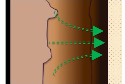
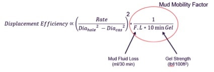
In practice the, dynamic fluid loss causes significant damage to the cement job by making more difficult to displace the mud in the hole.
This is explained in the following way:
Mud in the hole is composed of:
- Flowing mud
- Gelled mud
- Mud filter cake
The thicker the mud filter cake, the less impermeable it is, so the higher the % of gelled mud or the lower the % of flowing mud. To get the same displacement efficiency the pumping rate required will be higher.
Graphically this can be seen here:
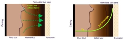
- What is the contribution of mud filter cake?
For intermediate sections, mud cake is likely far from thin and impermeable. In those cases, mud cake should be considered inexistent. Here, most cementers would sell you a train of pre flushes to achieve ‘mechanical’ and ‘chemical’ action to remove the mud filter cake. However, most of the time hardly doing anything.
For production zones, mud cake would probably be closer to its definition. It still needs to be removed, but the task in a friendlier annular gap (smaller) is supposed to be easier and mostly achieved by the action of the slurry itself (talking about abrasive action).
- What is the relationship between filtrate collected and API fluid Loss for cement slurries?
I will use my API 10B 2005 version (API Recommended Practice 10B-2 / ISO 10426-2) to explain this.
The API RP explains when to report FL as Calculated ISO Fluid Loss (tests that ‘blow out’ in less than the 30 min test interval) or ISO Fluid Loss (fluid loss is measured for a full 30 mins without ‘blowing out’). The FL value is doubled only if there is still fluid filtering at 30 mins if not, the FL is calculated. This is exactly what the procedure says. If at 30 mins, it hasn’t blown out, meaning N2 is not leaking, and it is liquid still dropping, the rate of filtration after 30 mins is not necessarily close to zero, because cement cake is not necessarily impermeable at that time. Now regarding the formula, it is easier to understand looking at the original one:
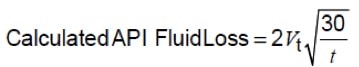
As you see, if there is still filtrate dropping (without ‘blowing out’ N2) at 30 mins (the end of test). The term in the square root becomes 1 and the filtrate is the double of the collected volume
The formula is my 2005 version is:
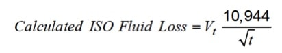
Where 10,944 is almost two times the square root of 30
Please if you have any questions or comments, just let me know in the space below.
Cheers
L. Diaz


Nice analysis Lenin. Well written and easily read. Thanks.
Thanks Jim, That is actually my objective to provide information that people can use.
Once again thanks for visiting my site and for the comment
Cheers
L. Diaz
Can describe to me how fluid loss actually helps keep water in cement? I have heard some explanations from some chemist saying is almost a mechanical process ? Can you give me your opinion ?
Thanks for the question. Thinking about the fluid loss test, there is always some cement slurry loss of filtrate (water from the cement) but as the test progresses the rate of filtration reduces with time. This reduction is caused by the building of a filter cake, whose thickness depends on its own permeability. So, to answer the question, fluid loss allows to keep the water in the cement because it builds a barrier or filter cake.
The permeability of the filter cake, i.e., it thickness, we can reduce it by the use of a dispersant to allow more order of the particles, the addition of smaller particles, a change in the particle distribution or the addition of polymers who act as gelled-particles filling the gap between other particles.
All this is static fluid loss.
In dynamic fluid loss, mainly when the filter cake is not so thin and impermeable as desired, the process is affected by erosion (removal of the filter cake) due to cement flow and loss of filtrate can remain constant.
In front of high permeable formation, depending on the thickness of the formation itself, even FL as low as less than 50 ml/30min can be still too high
Hope this helps, however if there are any more questions or clarification please do not hesitate to ask here
Cheers
L. Diaz
Hi Lenin,
very nice explanation about fluid loss. I would like to know why the value is always multiplied by 2.?
Thanks and Regards,
Suresh Choudhary
Suresh, thanks for your question
It is derived from the equation. with “t” as the time to blow out. If there is filtrate still dropping at end of test = 30min, the factor in the square root becomes (1) one. In this case the API filtrate is 2 times the filtrate collected.
Hopes this clarifies
Cheers
L. Diaz
Could you please explain what it means when we say we calculated 1500 ml/30 min as FL for a particular slurry. It is confusing when we see that initially the slurry used for lab testing was only 600 ml.
R.K, First of all I am truly sorry for this late reply, but I have been very busy with some projects. Please understand, this is not my normal response time.
Now coming back to your question, I can say that it is indeed confusing.
When measuring FL, there are two possible scenarios, one where nitrogen (used to applied pressure) doesn’t reach the bottom of the cell and flows out (blowout) and the other case when nitrogen does blowout. When nitrogen doesn’t blowout the ISO Fluid loss is the double of the collected amount of filtrate, but when the nitrogen does blowout there is a formula to calculate the FL and it is reported as Calculated Fluid Loss. And the sooner it blows out the higher the FL value. In other words, it means that a larger volume of slurry would have been required to collect at least 750 ml (for FL of 1500 ml/30min). So, the 1500 ml/30min is not linked to the 600 ml of slurry used for the test.
I hope is clear, and once again apologies for the delay
Cheers
L. Diaz
How was the formula for calculated fluid loss derived and why do we multiply by the square root of 30/t
The original formula is derived from Darcy’s Law and developed specifically for the concept of filter cake creation by Bourgoyne, 1991. The formula describes a liner relationship between the volume of filtrate and the square root of time.
In the API formula, we see two points in this line. One, that implies a filter cake is created (test running for 30min without “blowing out”) and another, where more slurry volume (above 600 ml) is required to form a filter cake (tests that “blow out” in less than 30min) so, that the following relationship exists: Volume fraction of solids in the slurry x Volume of slurry = Volume fraction of solids in the filter cake x Volume of filter cake. With the volume of filter cake = Thickness (varies with time) x Area; and also with the understanding that the volume of slurry in the formula refers to the volume of slurry carrying the solids to form the filter cake hence producing the volume of filtrate.
Hope this helps
L. Diaz
Why the YP is the important for oil cementing ?
Actually, I can’t understand about the YP’s meaning.
If YP is high, what is the positive thing in oil cementing? or why not?
I know that the additives like HEC is important for fluid loss restriction.
Which properties of HEC can affect ?
Thanks.
Hi T.H. Kim,
Yield Point in Bingham Plastic (flow model) is referred as the internal resistance of the fluid to start motion. When you pump (casing is in place), and fluid is moving up in the annulus, the fluid velocity is high (max) half way between casing and formation and low closer to the casing or formation. This fluid (mud, spacer or cement) closer to the casing or formation moving slower (actually zero velocity on the surface) is creating less friction pressure, so as you approach the casing or formation surface and velocity is slower and slower, at one point the velocity will be so slow and in consequence friction pressure that it won’t be able to move the fluid (friction pressure higher than the yield point). So, the lower the yield point the more fluid will be flowing. Since the spacer is pushing the mud, and the cement is pushing the spacer (and mud), their higher yield point, at certain pumping rate, is ensures mud is being displaced.
Let me know if you need further explanation
Cheers
L. Diaz
Why the YP is important for oil cementing?
Actually, I can’t understand about the YP.
If the YP is high, what is the positive in oil cementing?
I exactly want to know about the YP ..
and I know that HEC is important additives in oil cementing.
which properties of HEC is important in oil cementing?
thanks.
Hi T.H. Kim,
Yield Point in Bingham Plastic (flow model) is referred as the internal resistance of the fluid to start motion. When you pump (casing is in place), and fluid is moving up in the annulus, the fluid velocity is high (max) half way between casing and formation and low closer to the casing or formation. This fluid (mud, spacer or cement) closer to the casing or formation moving slower (actually zero velocity on the surface) is creating less friction pressure, so as you approach the casing or formation surface and velocity is slower and slower, at one point the velocity will be so slow and in consequence friction pressure that it won’t be able to move the fluid (friction pressure higher than the yield point). So, the lower the yield point the more fluid will be flowing. Since the spacer is pushing the mud, and the cement is pushing the spacer (and mud), their higher yield point, at certain pumping rate, is ensures mud is being displaced.
Let me know if you need further explanation
Cheers
L. Diaz
50ml / 30min API Fluid loss (lab volume), does it mean 50bbl in the field?
actually, 50ml means a 25ml water come out from the cell that has a 175ml cement slurry. now if you do the math that is 28% something Vol. by Vol., my question is, is this much fluid are really losing to the formation in the real time scenario? does it mean we are losing 25bbls of water to the formation? if yes, then why this is acceptable? if no, then why are we using this test method if it is not quantitatively and qualitatively consistent?
Hi Gio,
Indeed the method is referential, as it tries to simulate the loss of filtrate between the cement slurry once placed and the formation, acting as a permeable media. One thing to consider is that once the initial filter cake is formed, then what makes more difficult to filtrate further is the filter cake itself, as any filtrate will need to permeate thru the filter cake, which is becoming thicker. That is why the process follows an square root shape.
Now, you can convert the 50 ml/30 min to fluid per area, if you use the area of the filter in fluid loss cell … and then with fluid loss/area you can calculate what fluid the slurry is losing in front of a permeable zone of a known length (area of a cylinder of OH diameter). This numbers can be significant and leading to a defect in logs similar to microannulus.
In most cases, formation permeability is lower than the filter/mesh in the fluid loss cell, and to make sure we form a quick near-impermeable cement filter cake, we target low API fluid loss values. However if the formation permeability is high, in the order of Darcies, this is a problem requiring preventing and mitigating actions.
Cheers
L. Diaz
If we are pumping cement to control losses in the well what type cement slurry and Fluid loss should be used.
If we are considering cement to cure losses, it means that all drilling fluid based alternatives were already considered and didn’t work. The type of cement would be short TT, as simple as possible and no filtrate control
Dear Mr Diaz,
First of all, I want to say that I have learned a lot of important characteristics of cement slurry from you, and I want to say THANK YOU 🙂
I have one question about fluid loss. My slurry is mixture of microcement and aditives. In my filtrate, during fluid loss filtration, I dont have water, I have slurry. Micocement has very small particles, I think that is a reason for that.
What do you think? So, there is no (if I can say) free water, only cement slurry. When I open the cell, there is some cake, like clay.
Thank you in advance.
Greetings from Serbia
Nada
You can place a filter paper above the screen
Good Day Mr.Diaz,
Many thanks for interesting article related to fluid loss.
I am curious to knowing why API had recommended to use pressure constantly at 1000 psi (delta) for Fluid loss testing and also at 3000 psi for UCA or curing cube sample for mechanical compressive strength testing meanwhile each well have different BHP parameter.
Appreciate your prompt reply.
Thanks
Hi Alfian
For fluid loss keep in mind this is differential pressure. Equivalent to the difference between the hydrostatic in the annulus – the formation pressure. And what API is saying that you are 1000 psi overbalance, for example a 2 ppg difference @ 10,000 ft.
For the curing time, pressure will not have a significant role to change the outcome. Keep in mind, this curing is reproducing the slurry after placement.
Hi Lenin,
How can I get this latest excel sheet. Thanks
Regards,
rajesh kumar yogi