What is Rheology?
One of the most important things we, as oilwell cementers, must understand is rheology. In our line of business, Rheology is the key to cement coverage and zonal isolation; which is the sole goal of well cementing. However, as simple as this can be, it is incredible how easy it is underestimated and sometimes ignored entirely in our industry.
Unsurprisingly, it is not rare to hear cases of ‘unexpected’ cement returns in primary cementing, ‘unexpectedly’ higher TOC in liners, ‘unexpected’ lack of zonal isolation, etc. Only on very few occasions, the ‘unexpected’ designation of these situations gets attributed to Mother Nature or any other variable out of our control (no mystery here). More commonly, ‘unexpected’ would be the result of lack of awareness of the importance of rheology and fluids compatibility.
It is this reality that motivated me to write a post with some fundamental knowledge about rheology.
What is rheology? In general, we define rheology as:
The science of flow and deformation of material.
However, during my engineering studies, I remember that I liked this particular definition better:
All that happens in between Newton’s Law and Hooke’s Law.
Or:
The study of materials with both solid and fluid characteristics.
In well cementing, rheology affects:
- Cement slurry mixability and pumpability
- Cement coverage (mud displacement)
- Friction pressure estimation, ECD, losses prevention
- HHP requirements
There are two types of flow:
- Laminar flow
- Turbulent flow
The one we shall master as cementers is no doubt laminar flow. Why? It is merely because a turbulent flow is rarely achievable for any fluid. It’s even rarer for cement slurries, in situations where there is a high risk of channeling (like surface and intermediate casings)
I also have to mention plug flow…
… Which is sometimes heard out in the oilfield. Just one phrase for you: forget about it!!
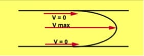
In Laminar flow, the velocity at the wall (casing and formation faces) is zero, and the maximum velocity is at the center of the annular gap.

In other words, essentially there is a natural tendency for fluid to channel when it flows laminarly. What should we do? Just prevent it channeling too much! How?
First of all, the standoff has to be maximized so that the flow path is maximized all around the annular gap.
Now, let’s see the mathematical representation of the shear stress (friction pressure) vs shear rate (flow rate). Or in simpler words how the fluid flows in response to force (pressure). There are four accepted models:
- Newtonian
- Bingham Plastic
- Power Law
- Herschel–Bulkley (provides a better fit in most occasions for cement slurries)
The use of computer simulation software
Most computer simulation software used in well cementing provides a representation of the flow models for each fluid’s rheological data entered. This data comes from laboratory measurements following API RP 10B-2 / ISO 10426-2 procedure. In some simulation software, you even have the opportunity to select which model better fits experimental values manually. Proper selection of the model is an essential step as it affects the validity of the simulator output.
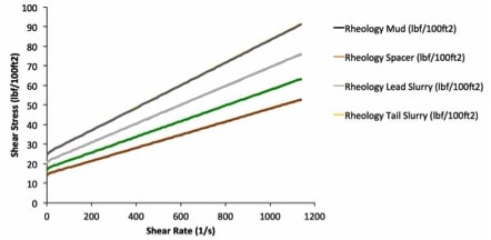
The following chart is perhaps the first most important tool (simulator output) we have to ensure proper fluid placement (rheology). Here we must understand that the Oilwell Cementing Engineer should work closely with the laboratory to generate the best-fit solution for fluids design (spacer and cement slurries).
A common error these days is that design engineers do not provide the lab with a starting ‘target’ fluid rheology. This means that whatever comes from the lab is assumed to be ok and entered in the software, but there is no check of the following chart to see if fluids will progressively displace one another. Rheological properties are just as crucial as thickening time and density, they have a direct effect on job success (cement coverage = zonal isolation).

This image, in particular, is an ideal representation, where each fluid has higher rheology (friction pressure) than the previous (ahead), starting with the mud. This additional friction pressure in each fluid behind is vital to prevent channeling.
The maximum allowable ECD sets the limitation
Here are some recommendations:
- Lower the rheology of the mud as low as practically possible (‘practically possible’ usually means, that the mud retains some carrying capacity or to prevent solids settling) only after the hole is clean. It is a common practice for cementers to request/suggest a certain Yp (yield point) value in the mud. We must understand that Yp for the mud engineer is not the same as the Yp for the formed. Why? Because Yp for the mud engineer is “Θ300 – Pv”, but for the Cementing Engineer (using software) it’s a parameter (for Bingham Plastic; the Offset at 0 shear rate) in a mathematical equation. The Yp value from the simplified method used by the mud engineer will be typically higher than the one obtained from the mathematical model. Conclusion: When the mud engineer tells you the Yp, ask for the readings instead. Don’t input the Yp value directly in the software.
- For surface and intermediate casing, simplify your fluids. For instance, if we use a WBM, consider removing the spacer. Compatibility between mud and lead slurry won’t likely be an issue (always check).
- Get a well-documented FG or losses margin.
- Pick fluids density wisely. Don’t limit yourself to generic values.
- Choose the TOC for the Tail slurry as low as possible, if no requirement to cover a formation in particular.
- I have to say; pumping rate should not be compromised, always try to keep it as high as 7 to 8 bpm, especially when the cement is in the annulus.
Now, some words about fluids compatibility
Fluids compatibility is the change in rheology that happens down-hole due to fluids intermixing, and it can quickly make your job design (simulation) obsolete. It has particular significance in the presence of OBM, high density or high salinity muds; more common for deeper sections.
We need to test fluids compatibility following API RP 10B-2 / ISO 10426-2 section 16. However, the best approach is to avoid any incompatibility between mud and the cement slurries, even if we use a spacer (don’t trust the spacer will keep your slurries away from any contact with the mud).
Any incompatibility will alter the flow of fluids creating viscous or increased-gel byproducts every time an interface is formed as a result of channeling (higher viscosity or gelled residues are left behind bringing new fresh fluids in contact again as flow continues).
I hope you find this post helpful.
Please leave your feedback, comments or questions
Cheers
L. Diaz


Hello Lenin,
Nice subject. In order to avoid intermixing of the fluids, rheological hierarchy is important. The most challenging thing is to achieve the rheological hierarchy under BHCT. As the fluids get heated, they lose rheological characteristics and thin down. Due to use of multiple additives, this effect is much prominent in cement slurries. This is the major challenge as if the additives responsible for giving body to slurry are increased, the surface rheology increases to the level that makes surface mixing difficult.
Thanks,
Kedar
Another great contribution Kedar. Thanks.
That is a very important challenge, specially in high temperature wells/sections, and I believe a good topic for a post.
I will soon write about it, including some of the “solutions” that can be implemented. Hopefully we will also have other experienced people joing the discussion with more ideas and cases.
Cheers
L. Diaz
Yes sir, that’llbe a good idea. Thanks.
Hello Lenin, I recently learnt the calculations of ECDs. But off late, I came across a term called ‘Dynamic Hydrostatic Pressure’ during pumping. Which I believe is different from the static hydrostatic pressure of the fluid column and it is something different from Frictional pressure which is calculated from Rheology and fluid model formulas. Please let me know if you can help me in understanding what exactly is ‘Dynamic Hydrostatic Pressure’ or share some online website links or literature on this topic to study more?
Keshav, thanks for this question.
Not really sure about how is this term related to fluid dynamics in well cementing. In different applications, ‘Dynamic Hydrostatic Pressure” is associated with a pressure way moving or bouncing inside a confined fluid, more like pressure vibration or even pulsation, which will cause variations in hydrostatic pressure due to momentum conservation.
Perhaps one similarity in our environment, a cementing operation, is called “water hammer“.
In our case, the static component is provided by hydrostatic pressure and the dynamic component is derived from flow, frictional pressure. Combined they produce what we know as ECD.
Hope this helps
Cheers,
L. Diaz
I came across Dynamic hydrostatics in ‘Bernoulli’s theorem’ of fluid flow (Static pressure+Dynamic hydrostatic pressures) where in the kinetic energy of moving fluid is called Dynamic hydrostatic. However in that theorem they have assumed the viscosity and compressibility of the fluid to be NIL. We do consider the annular velocity in calculating the frictional pressures. So, as you mentioned the dynamic pressure must already been considered while calculating the frictional pressures along with the fluid Rheology and flow models.
Thanks Lenin.
Thanks Keshav, for this very interesting discussion.
Hi Lenin,
Another great post. As a drilling engineer who is much interested in cementing, your blogs are a treasure trove. One thing I would like to ask ” Have you came across clients asking for specific rheological properties from cementing services.?”
The point is since you mentioned that design engineers do not provide target rheologies for labs to design across. I think clients can also define specific rheological properties for cement slurries? Is it a good idea or we should leave this to cementers?
Hi Usama, thanks for the comments and for reading my blog. This is a good question, yes, I have. These are customers that either have a cementing specialist or a written cementing guideline.
Typically, it all start with the rheological properties of the mud (fluid in the well) which must be entirely displaced and replaced with cement. This set the values for the spacer (it must displace the mud ahead), the lead slurry (must displace the spacer and the mud) and the tail slurry (must displace the lead slurry, the spacer and the mud). Ideally, each fluid should only see the fluid ahead (assuming all are doing the job), but due to channeling a fluid ahead can be left behind encountering the next fluid in the trail (these are the cases when cement slurry gets in contact with mud).
In summary, in your case as a DE, rather than request rheology, you shall request the cementing engineer explains to you how the cement is being placed and what is the final cement coverage (Here, the cementing engineer would use the simulator output) .. then he will blame you because you are not running enough centralizers, which should lead to some healthy discussion and the assessment of scenarios; where a combination of rheology and centralization should be decided to achieve the job objective (basically, where the good zonal isolation – best bonded cement – is needed).
Cheers
L. Diaz